Place of Origin: | China |
Brand Name: | OEM |
Model Number: | SID-2CM |
Minimum Order Quantity: | 10 pcs |
---|---|
Price: | contact |
Packaging Details: | Carton box |
Delivery Time: | 10days |
Payment Terms: | T/T |
Supply Ability: | 5000PCS / month |
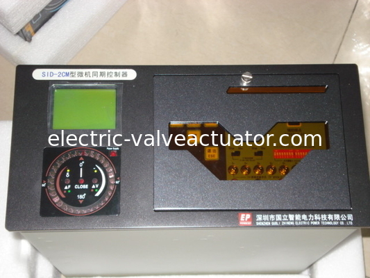
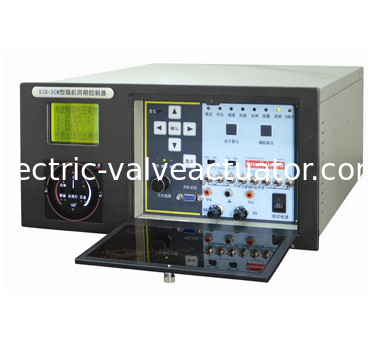
SID-2CM generator line multiplexing microcomputer synchronization device
1 There are twelve channels to be used for 1-12 units power generator or
power lines paralleling in a device, type and attribute of paralleling can be distinguished.
2 Setting parameters: breaker time; Allowable voltage differential; over voltage protecting value;
Allowable frequency difference value; frequency control coefficient; voltage control coefficient;
Allowable power angle;Incomer and busbar TV rated voltage; shift busbar TV phase angle;
low voltage lock values on both sides of paralleling point; single side or both sides no-voltage operating;synchroscope funtion; Control pulse width for same frequence;breaker name .
3 The device can ensure the first zero phase differential appearing to be seized while differential paralleling
(between generator and busbar or two synchronous lines.) and make paralleling without impacting;
4 The device can make a fast paralleling of generators through the way it can leads frequency differential and
voltage differential into the Allowable range according to the theory of fuzzy control;
5 When paralleling will begin at once only if the power angle and the voltage difference are less than the
allowable values when paralleling between synchronous lines, otherwise , there must be a wait and signal,
whether it was differential frequency or identical frequency can be distinguished by the device automatically;
6 The device can make self-test when running timely and automatically, it can also alarm and display if error;
7 Alarming when TV open-circuit and locking the operation of synchronizing and non-voltage closing;
8 An acceleration control instruction can be given automatically when frequency is identical during the
process of paralleling of generators in order to cancel the identical frequency condition.
Paralleling of anti-power will be never appeared surely if necessary;
9 The device will display these data – real measuring time a breaker circuit takes when closing and the
last eight real measuring values recorded in every channel after accomplishing the paralleling in
order to make certain the accuracy of the time it takes when breaker closing.
The time for breakers’ closing will not be recorded when it is identical frequency paralleling.
10 Communication accesses and communication agreements will be provided between the device
and the host computer (RS-232, RS-485), in order to meet the requirements the device will be admitted into the DCS system.
11 The device can work even though under an awful conditions owing its methods of complete
and strict insulation ways on electromagnet and photo electricity;
12 AC or DC can be as power supply of the device and the device can adapt itself to 48V—220V AC
or DC power supply automatically;
13 Checking and testing can be made directly without any other apparatus because the module
demanded is already in the device;
14 One side or both sides no-voltage close breaker can be accomplished according to the instructions from the host computer;
or both sides no-voltage close breaker from operating the front panel switch..
15 To be used as a intelligent synchroscope.
Technical index
1. The input of the TV secondary voltage on both sides of the circuit breaker can be either phase voltage or line voltage. The sampled TV signals on both sides have no common ground inside the device and are independent of whether the TV secondary voltage is common ground or not. Each parallel point can set the angle of the secondary voltage of the system side TV separately, without the need to install isolation transformers and angle transformers.
2. All input switch values (parallel point selection, remote reset, start synchronous operation, confirmation of single side voltage free closing, confirmation of voltage free air closing, auxiliary contacts of circuit breaker, etc.) are normally open air contacts.
3. The output switch quantity (acceleration, deceleration, boost, closing, power angle exceeding limit, alarm, power loss, etc.) control signal uses a small electromagnetic relay normally open air contact ("power loss" is normally closed), with a contact capacity of 220V AC, 5A or 220V DC, 0.5A. When using optical isolation contactless MOSFET relays in the closing circuit, it is 600V DC, 6A.
4. One RS-232 and one RS-485 communication interface each.
5. The working power supply can be either 110-220 volts AC/DC, with a power consumption not exceeding 30 volt amperes.
6. Insulation strength: weak current circuit to ground: 500V 50Hz 1 Min
Strong current circuit to ground: 2000V 50Hz 1 Min
Between strong and weak electrical circuits: 1000V 50Hz 1 Min
7. Working environment: Working temperature: -10 ℃~55 ℃
Storage temperature: -20 ℃~70 ℃
Relative temperature: not greater than 90%.
Contact Person: Ms. Biona
Tel: 86-755-82861683
Fax: 86-755-83989939
APF7.820.077C PCB for ESP voltage controller spare, voltage and current signal process
380V AC Industrial Frequency Power ESP Controllers EPIC-III Controller Sampling Board, Trigger Board
Ignition Cble XDL-l B Explosion Proof High Performance Ignition System Device Cable Length 2, 3, 6m
Coal Feeder Spare main board , CPU board 9224 / CS2024 / EG24 ( Micro board )
Coal Feeder Spare degree probe for 9224 / CS2024 coal feeder, CS19900, C19900, CS8406
Coal Feeder Spare CS2024 and 9424 special coal feeder belt for electronic weighing type